Microwave Transmission Line Considerations for Vehicle Applications
by Times Microwave
Originally published in Microwave Product Digest
Whether on land, sea, or air, RF transmission lines installed in mobile platforms must be able to operate in severe conditions, including wide temperature and altitude ranges and high vibration exposures. They must be made using materials suitable for use in these demanding environments, and for reasons of safety, must not support flame or emit toxic vapors when burned. Commonly referred to as the Group A Cables, they form the critical links for a wide range of RF systems being installed on today’s high tech multifunction platforms.
Making Interconnect Choices
Proper product selection begins with understanding the RF signals to be carried, beginning with the frequency range. To assure proper transmission line performance, cables must be used that support Transverse Electro-Magnetic (TEM) mode signal transfer. This can be evaluated by comparing the highest frequency signal being carried to the cut-off frequency of the cable. Cut-off frequency is determined using a simple formula and a few parameters from the specification sheet of the cable being considered:
Cable specs needed: cable velocity of propagation (Vg as a fraction of the speed of light), diameter of center conductor (d, in inches) and the diameter of the cable dielectric (D, in inches)
TEM Fmax in GHz = (7.5 x Vg) / (d + D)
This calculation determines the maximum frequency at which a particular cable can operate in the TEM only mode. Calculated using cable dimensions, this first requirement is used to set the upper limit for acceptable cable size in the application.
At this point, other electrical operating requirements are considered to find the optimum system solution.
Often, the most important considerations are insertion loss, power handling and phase stability of the transmission lines. Larger cable sizes provide lower loss for a given run length. Although the maximum acceptable cable size has been determined, it may be further reduced by physical installation limitations. Given that the cable size is limited, improving the low loss performance is then achieved through optimization of the conductors and dielectrics with which the cable is manufactured. In many systems, it is not only the total amount of signal that is lost which is critical, but also the balancing of transmission line losses between antennas located at various areas of a vehicle. Balanced losses can be achieved among several differing cable runs through the judicious selection of cable lengths and sizes. High power handling may be required for transmit applications, and the ability of the cable to support the peak and Continuous Wave (CW) power levels needed must be reviewed. Peak power capability is related to the voltage handling capability of the transmission line. CW power handling is a function of the transmission line’s ability to minimize, withstand and dissipate heat. Heat generation is directly related to the insertion loss, and therefore the size of the cable. However, as the necessary cable size approaches the allowed maximum, the designer is forced to rely on higher temperature materials supplemented with heat sinking to handle high power levels. Systems that rely on signal phase matching and tracking, require the electrical length of interconnect designs to as a minimum change predictably with varying temperature, and optimally change as little as possible in the same conditions.
Coaxial Cable Design Considerations
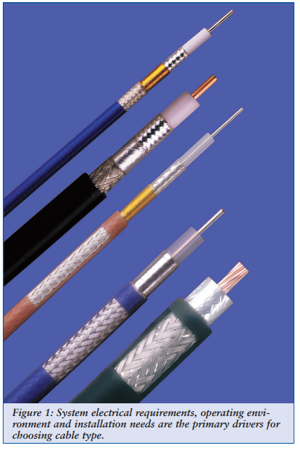
A coaxial cable consists of an inner electrical conductor (or center conductor) surrounded by a dielectric medium, an electrical shield (or outer conductor) and, in most cases, a separate environmental protection layer (jacket or outer jacket). Understanding all of the operating requirements allows these components to be optimized for the environment and application.
Center Conductor
At microwave frequencies currents travel on the outside surface of the center conductor and inside surface of the outer conductor. Silver, being a highly conductive material, is most often used as the outer plating of the center conductor. The inner core of the center conductor can then be tailored to support the application. Where weight is a consideration, as often occurs in airframe applications, using high strength copper clad aluminum alloys reduces overall center conductor weight by more than 50%. Small center conductor cables often use copper clad steel as the core for added strength. In the case of RG402 cable, the copper clad steel center conductor can be used as the center contact of an SMA connector, performing double duty.
Stranded center conductors are employed in applications requiring high flexibility and/or a low bending moment. The tradeoff in this choice is increased cable attenuation and the potential for structural reflections (or VSWR spikes) occurring at ½ wavelengths of the conductor’s lay length. As with solid conductors, the core of stranded conductors can be optimized for the application. One technique to reduce weight is to cable the individual conductor strands around a flexible lightweight non-metallic (non-conductive) core.
Dielectric
Polyethylene (PE) and Polytetrafluoroethylene (PTFE) based materials are the most common cable dielectric materials. While both can be used in solid form when extruded onto the center conductor, today’s low loss cables use either PE foam or low density PTFE material, either extruded or tape wrapped on the center conductor. PTFE, while more costly, provides the lowest loss, is flame resistant and has an upper temperature in excess of +200 degrees C, compared to a maximum of +85 C for PE. On the downside, it does emit toxic halogen fumes under extremely high heat, and for this reason is normally avoided for shipboard applications. For temperatures above 250 degrees C, as in cables routed near an engine, Silicon dioxide (Si02) is the typical choice for cable dielectric use for its extreme temperature capabilities and good electrical properties.
Recent developments include new dielectrics that have been optimized to minimize phase change over temperature, historically a problem with PTFE cable designs. PTFE dielectrics exhibit large phase changes between 19 and 23 degrees C. This characteristic is particularly important for phase critical runs in any vehicle where cables may not be operating simultaneously at precisely the same temperature.
Outer Conductors
Most vehicle applications incorporate flexible cables that are easily installed and routed, instead of pre-formed rigid cable designs. Flexible, low loss, high shielded outer conductors can be made in several different ways. A thin aluminum laminate is the lowest cost approach, and provides good performance for applications operating up to 6 GHz. While braids of round wire can serve as outer conductors, lower loss Silver plated copper strip conductors can be used instead, and either braided, helically, or spiral wrapped onto the dielectric. Additional braids over the RF path provide added shielding, physical strength and a means to capture the connectors. In applications where weight is most critical, Kevlar™ or other high strength and lightweight materials can be incorporated into the braid design to displace heavier metal components.
Outer Protection
A properly designed jacketing system is required to protect the RF cable against the environment. Airframe cables are most typically jacketed with a fluoropolymer extrusion such as FEP or PFA. Additional protection is often applied with a braid incorporating Nomex ™ or other similar material. Cables highly susceptible to handling damage can incorporate a high strength spring to increase strength. Shipboard and ground based cables do not typically require high temperature performance, but often do require jackets that do not contain any halogens, precluding the use of the fluoropolymer materials in favor of specially formulated materials that meet the low smoke and zero halogen requirements of MIL-DTL-17.
Connector Selection
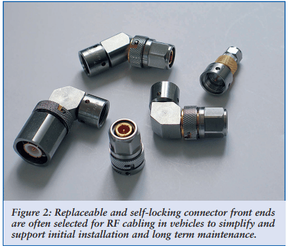
While a wide range of connector types are used for vehicle system interconnects, Type N and TNC connectors are the most common interfaces needed. They are suitable for a wide range of cable sizes, and provide a reliable and robust connection. Though both originated over 50 years ago, today’s connectors have been enhanced for performance to 18 GHz, incorporating features that improve reliability and maintainability. Particularly useful among these features are self-locking mechanisms which prevent connections from coming loose under vibration. Prior to this innovation, connector coupling nuts had to be individually secured with small lockwires - a time consuming operation and a potential source of contaminating Foreign Object Debris (FOD). Connectors with replaceable front end heads are now widely used, and permit easy replacement of damaged interfaces, orientation of angle connectors, or the quick substitution of one connector style for another. Titanium connectors, offering the ultimate in weight reduction and reliability are being employed in the most critically weight sensitive or corrosion resistant applications. Recent developments include connectors that replace threaded connections with quick disconnect coupling mechanisms without compromising performance.
Connectors for high power applications require special considerations to handle the associated heat generation and higher voltages. The limiting factor for temperature handling of a TNC connector is the PTFE dielectric. CW power handling is increased by replacing it with a higher temperature material such as fluoroloy, or if terminated onto a SI02 dielectric cable, eliminated altogether. Increasing the voltage handling of a connector is done by eliminating potential air gaps with overlapping dielectrics.
Multiport connectors have become a staple for size, weight and ease of installation and maintenance. High performance microwave contacts are available for MIL-C-38999, ARINC and other common standard connector shells, or may be custom designed to fit a specific footprint, or even machined as part of a mounting structure.
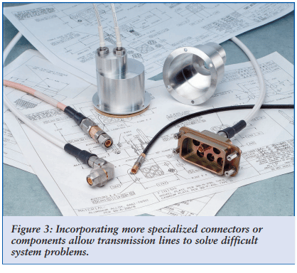
An offshoot of multiport technology are blindmate antenna mounts that that permit simple replacement of an antenna from the exterior of an airframe or other vehicle without the need to pull cables through the mounting holes in order access and disconnect them, eliminating the resultant cable damage that often requires a major replacement effort.
Additional options for transmission lines include integrating active and passive devices into the system interconnects, to enhance performance or solve a problem not taken into account in the original system design. Typical components used for this purpose include LNA’s, attenuators, equalizers, filters and lightening protection components, which can be incorporated in any combination into a single device.
Special Characteristics
Many of the optional components and characteristics identified throughout this article allow you to resolve multiple system problems, simply by choosing the right transmission line for your application. One way to solve seemingly insurmountable problems is to take a fresh look at the many options that are available among the standard components that designers too often simply take for granted. Also, don’t forget to ask your cable supplier’s applications engineers for their suggestions. You may find that the solution to your next interconnect challenge is only a phone call away.
Complete Transmission Lines
Choosing the right transmission line for any vehicle application requires attention to the details of intended use, operating environment, performance, installation and maintenance requirements, and the resulting impact of those details on the materials and design of the interconnecting cables. Cable and connector materials and construction details play a major role in the success of a cabling system. There are many choices available to the designer to develop a truly optimized transmission line interconnect system, and the time spent understanding and considering the impact of all factors will be greatly rewarded.
Subscribe to our newsletter!
Interested in receiving email newsletters and other updates from Times? Subscribe now!